Nissan Maxima Service and Repair Manual: Can communication system
System Description
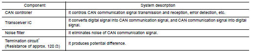
- CAN communication is a multiplex communication system. This enables the system to transmit and receive large quantities of data at high speed by connecting control units with two communication lines (CAN-H and CAN-L).
- Control units on the CAN network transmit signals using the CAN communication control circuit. They receive only necessary signals from other control units to operate various functions.
- CAN communication lines adopt twisted-pair line style (two lines twisted) for noise immunity.
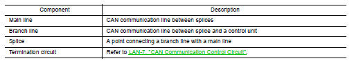
System Diagram
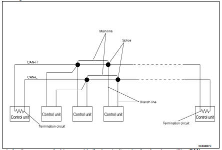
Each control unit passes an electric current to the termination circuits when transmitting CAN communication signal. The termination circuits produce an electrical potential difference between CAN-H and CAN-L. CAN communication system transmits and receives CAN communication signals by the potential difference.
*: These are the only control units wired with both ends of CAN communication system.

 Diag on can
Description
"Diag on CAN" is a diagnosis using CAN communication instead of previous DDL1
and DDL2 communication
lines, between control units and diagnosis unit.
System Diagram
...
Other materials:
EBD
System Diagram
System Description
Electric Brake force Distribution functions as follows:
ABS actuator and electric unit (control unit) detects subtle
slippages between the front and rear wheels during
braking. Then it electronically controls the rear braking force (brake fluid
pr ...
Precaution
Precaution for Supplemental Restraint System (SRS) "AIR BAG" and "SEAT
BELT
PRE-TENSIONER"
The Supplemental Restraint System such as "AIR BAG" and "SEAT BELT
PRE-TENSIONER", used along
with a front seat belt, helps to reduce the risk or severity of injury to the
driver ...
Precaution
PRECAUTIONS
Precautions for Trouble Diagnosis
CAUTION:
Never apply 7.0 V or more to the measurement terminal.
Use a tester with open terminal voltage of 7.0 V or less.
Turn the ignition switch OFF and disconnect the battery cable from the
negative terminal when checking the harness.
P ...
Nissan Maxima Owners Manual
- Illustrated table of contents
- Safety-Seats, seat belts and supplemental restraint system
- Instruments and controls
- Pre-driving checks and adjustments
- Monitor, climate, audio, phone and voice recognition systems
- Starting and driving
- In case of emergency
- Appearance and care
- Do-it-yourself
- Maintenance and schedules
- Technical and consumer information
Nissan Maxima Service and Repair Manual

0.0089