Nissan Maxima Service and Repair Manual: U1000 CAN comm circuit
Description
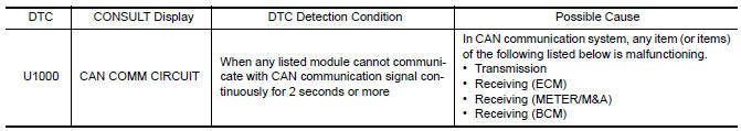
DTC Logic
DTC DETECTION LOGIC
Diagnosis Procedure
1. PERFORM SELF DIAGNOSTIC
- Turn ignition switch ON and wait for 2 seconds or more.
- Check "Self Diagnostic Result" of IPDM E/R.

 B2098 ignition relay on stuck
DTC Logic
DTC DETECTION LOGIC
1.PERFORM DTC CONFIRMATION PROCEDURE
Turn the power supply position to start under the following
conditions and wait for at least 1 second.
CVT selecto ...
Other materials:
Steering switch
Removal and Installation
REMOVAL
Remove the driver airbag module. Refer to SR-12, "Removal and
Installation".
Remove the steering wheel audio control switch screws (A).
Release the steering wheel audio control switch harness clips
(B).
Remove the steering wheel audio contr ...
Indicator lights
For additional information, refer to "Vehicle information
display" in this section.
Front fog light indicator
light
(green)
The front fog light indicator light illuminates when
the front fog lights are on. For additional information,
refer to "Fog light switch" in this section.
Front passen ...
Three-point type seat belt with retractor
WARNING
Every person who drives or rides in this
vehicle should use a seat belt at all
times. Children should be in the rear
seats and in an appropriate restraint.
Do not ride in a moving vehicle when
the seatback is reclined. This can be
dangerous. The shoulder belt will not
be ag ...
Nissan Maxima Owners Manual
- Illustrated table of contents
- Safety-Seats, seat belts and supplemental restraint system
- Instruments and controls
- Pre-driving checks and adjustments
- Monitor, climate, audio, phone and voice recognition systems
- Starting and driving
- In case of emergency
- Appearance and care
- Do-it-yourself
- Maintenance and schedules
- Technical and consumer information
Nissan Maxima Service and Repair Manual

0.0059