Nissan Maxima Service and Repair Manual: Hands-free phone system
System Diagram
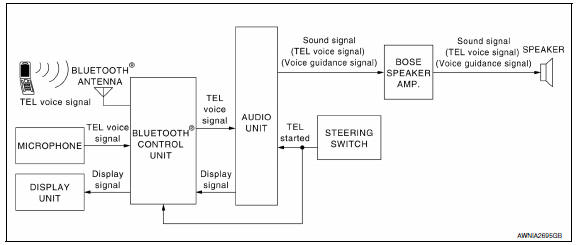
System Description
Refer to the Owner's Manual for Bluetooth telephone system operating instructions.
NOTE: Cellular telephones must have their wireless connection set up (paired) before using the Bluetooth telephone system.
Bluetooth telephone system allows users who have a Bluetooth cellular telephone to make a wireless connection between their cellular telephone and the Bluetooth control unit. Hands-free cellular telephone calls can be sent and received. Some Bluetooth cellular telephones may not be recognized by the Bluetooth control unit. When a cellular telephone or the Bluetooth control unit is replaced, the telephone must be paired with the Bluetooth control unit. Different cellular telephones may have different pairing procedures. Refer to the cellular telephone operating manual.
BLUETOOTH CONTROL UNIT
When the ignition switch is turned to ACC or ON, the Bluetooth control unit will power up. During power up, the Bluetooth control unit is initialized and performs various self-checks. Initialization may take up to 20 seconds.
If a phone is present in the vehicle and paired with the Bluetooth control unit, Nissan Voice Recognition will then become active. Bluetooth telephone functions can be turned off using the Nissan Voice Recognition system.
STEERING WHEEL AUDIO CONTROL SWITCHES
When buttons on the steering wheel audio control switch are pushed, the resistance in steering wheel audio control switch circuit changes, depending on which button is pushed. The Bluetooth control unit uses this signal to perform various functions while navigating through the voice recognition system.
The following functions can be performed using the steering wheel audio control switch:
- Initiate self-diagnosis of the Bluetooth telephone system
- Start a voice recognition session
- Answer and end telephone calls
- Adjust the volume of calls
MICROPHONE
The microphone is located in the roof console assembly. The microphone sends a signal to the Bluetooth control unit. The microphone can be actively tested during self-diagnosis.
AUDIO UNIT
The audio unit receives signals from the Bluetooth control unit and sends audio signals to the speakers
Component Parts Location
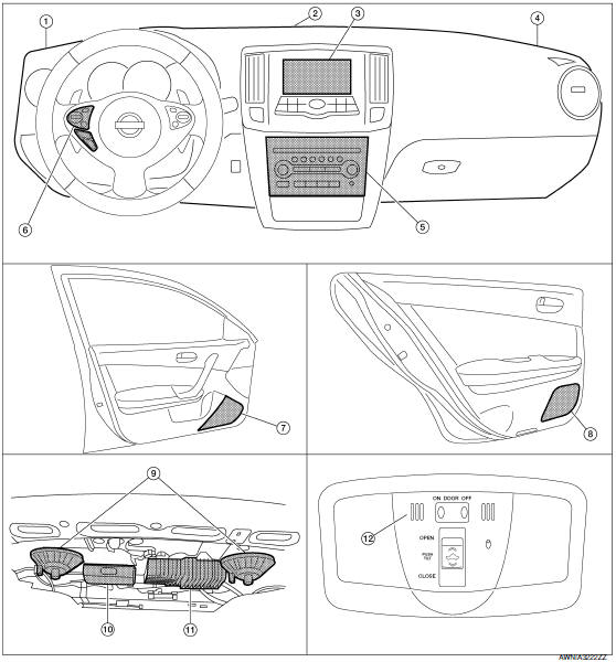
- Tweeter LH M51
- Center speaker M130
- Display unit M109
- Tweeter RH M52
- Audio unit M132, M135
- Steering wheel audio control switches
- Front door speaker LH D3 RH D103
- Rear door speaker LH D202 RH D302
- Rear subwoofer LH B106 RH B107
- Bluetooth control unit B125, B130, B131
- BOSE speaker amp. B109, B110 12. Microphone R7
Component Description
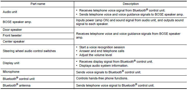
 Audio system
System Diagram
System Description
AUDIO SYSTEM
The audio system consists of the following components
Audio unit
Display unit
Bluetooth control unit
Window antenna
BOSE speaker amp.
...
 Diagnosis system (audio unit)
Diagnosis Description
Self-diagnosis mode can perform the following items.
Versions display
Channel check diagnosis
Key check diagnosis
AV communication diagnosis
VERSIONS DISPLAY FUNCTI ...
Other materials:
Servicing air conditioner
The air conditioner system in your NISSAN vehicle
is charged with a refrigerant designed with
the environment in mind.
This refrigerant does not harm the earth's
ozone layer.
Special charging equipment and lubricant is required
when servicing your NISSAN air conditioner.
Using improper refr ...
Water pump
Exploded View
Water pump
O-rings
Timing chain tensioner
Intake valve timing control solenoid
valve cover (RH) (bank 1)
Water pump cover
Removal and Installation
WARNING:
Do not remove the radiator cap when the engine is hot. Serious burns could occur
from high pressure
co ...
B2578, B2579 in-vehicle sensor
Description
In-vehicle Sensor
The in-vehicle sensor (1) is located on instrument lower cover
(LH).
It converts variations in compartment air temperature drawn from
the aspirator into a resistance value. It is then input into the A/C
auto amp.
In-vehicle Sensor Circuit
Aspira ...
Nissan Maxima Owners Manual
- Illustrated table of contents
- Safety-Seats, seat belts and supplemental restraint system
- Instruments and controls
- Pre-driving checks and adjustments
- Monitor, climate, audio, phone and voice recognition systems
- Starting and driving
- In case of emergency
- Appearance and care
- Do-it-yourself
- Maintenance and schedules
- Technical and consumer information
Nissan Maxima Service and Repair Manual

0.0059