Nissan Maxima Service and Repair Manual: Front tweeter
Removal and Installation
REMOVAL
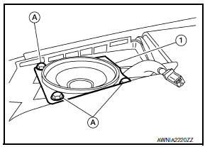
- Remove the front pillar finisher. Refer to INT-24, "Removal and Installation".
- Remove the front tweeter speaker grille. Refer to IP-10, "Exploded View".
- Remove the front tweeter speaker screws (A).
- Pull out front tweeter speaker (1), disconnect the harness connector from the front tweeter speaker and remove.
INSTALLATION
Installation is in the reverse order of removal.
 Aux in jack
Removal and Installation
REMOVAL
Remove the center console assembly. Refer to IP-14, "Removal and
Installation".
Remove the auxiliary input jacks screws (A) and auxiliary input ...
 Center speaker
Removal and Installation
REMOVAL
Remove the center speaker grille, using a suitable tool.
Remove the center speaker screws (A).
Pull out the center speaker (1), disconnect the harness con ...
Other materials:
Automatic air conditioner system
System Diagram
CONTROL SYSTEM
The control system consists of input sensors, switches, the A/C auto amp.
(microcomputer) and outputs. The
relationship of these components is as shown in the figure below:
System Description
CONTROL OPERATION
Display
The operation status of the HVAC system ...
Navigation system
System Diagram
System Description
NOTE:
Refer to NAVI System Owner's Manual for system operation.
The navigation system periodically calculates the vehicle's current position
according to the following three
signals: Travel distance of the vehicle as determined by the vehicle s ...
Precaution
PRECAUTIONS
Precaution for Supplemental Restraint System (SRS) "AIR BAG" and "SEAT
BELT
PRE-TENSIONER"
The Supplemental Restraint System such as "AIR BAG" and "SEAT BELT PRE-TENSIONER",
used along
with a front seat belt, helps to reduce the risk or severity of injury to ...
Nissan Maxima Owners Manual
- Illustrated table of contents
- Safety-Seats, seat belts and supplemental restraint system
- Instruments and controls
- Pre-driving checks and adjustments
- Monitor, climate, audio, phone and voice recognition systems
- Starting and driving
- In case of emergency
- Appearance and care
- Do-it-yourself
- Maintenance and schedules
- Technical and consumer information
Nissan Maxima Service and Repair Manual

0.0055