Nissan Maxima Service and Repair Manual: P0122, P0123 TP sensor
Description
Electric throttle control actuator consists of throttle control motor, throttle position sensor, etc. The throttle position sensor responds to the throttle valve movement.
The throttle position sensor has two sensors. These sensors are a kind of potentiometer which transform the throttle valve position into output voltage, and emit the voltage signal to the ECM. The ECM judges the current opening angle of the throttle valve from these signals and controls the throttle valve opening angle in response to driving conditions via the throttle control motor.
DTC Logic
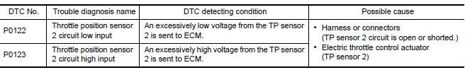
DTC DETECTION LOGIC
NOTE: If DTC P0122 or P0123 is displayed with DTC P0643, first perform the trouble diagnosis for DTC P0643.
DTC CONFIRMATION PROCEDURE
1.PRECONDITIONING
If DTC Confirmation Procedure has been previously conducted, always perform the following before conducting the next test.
- Turn ignition switch OFF and wait at least 10 seconds.
- Turn ignition switch ON.
- Turn ignition switch OFF and wait at least 10 seconds.
TESTING CONDITION: Before performing the following procedure, confirm that battery voltage is more than 8 V at idle.
2.PERFORM DTC CONFIRMATION PROCEDURE
- Start engine and let it idle for 1 second.
- Check DTC.
Diagnosis Procedure
1.CHECK GROUND CONNECTION
- Turn ignition switch OFF.
- Check ground connection E9.
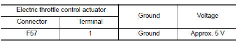
2.CHECK THROTTLE POSITION SENSOR 2 POWER SUPPLY CIRCUIT
- Disconnect electric throttle control actuator harness connector.
- Turn ignition switch ON.
- Check the voltage between electric throttle control actuator harness connector and ground
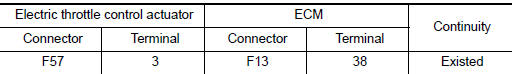
3.CHECK THROTTLE POSITION SENSOR 2 GROUND CIRCUIT FOR OPEN AND SHORT
- Turn ignition switch OFF.
- Disconnect ECM harness connector.
- Check the continuity between electric throttle control actuator harness connector and ECM harness connector.
- Also check harness for short to ground and short to power.
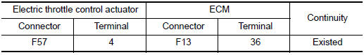
4.CHECK THROTTLE POSITION SENSOR 2 INPUT SIGNAL CIRCUIT FOR OPEN AND SHORT
- Check the continuity between electric throttle control actuator harness connector and ECM harness connector.
- Also check harness for short to ground and short to power.
5.CHECK THROTTLE POSITION SENSOR
6.REPLACE ELECTRIC THROTTLE CONTROL ACTUATOR
- Replace electric throttle control actuator
7.CHECK INTERMITTENT INCIDENT
Component Inspection
1.CHECK THROTTLE POSITION SENSOR
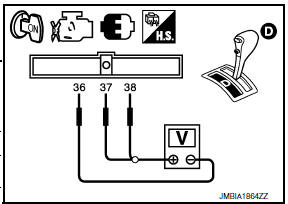
- Turn ignition switch OFF.
- Reconnect all harness connectors disconnected.
- Perform EC-21, "THROTTLE VALVE CLOSED POSITION LEARNING : Special Repair Requirement".
- Turn ignition switch ON.
- Set selector lever to D position.
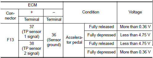
- Check the voltage between ECM harness connector terminals under the following conditions.
2.REPLACE ELECTRIC THROTTLE CONTROL ACTUATOR
- Replace electric throttle control actuator
Special Repair Requirement
1.PERFORM THROTTLE VALVE CLOSED POSITION LEARNING
2.PERFORM IDLE AIR VOLUME LEARNING
 P0117, P0118 ECT sensor
Description
The engine coolant temperature sensor is used to detect the engine
coolant temperature. The sensor modifies a voltage signal from the
ECM. The modified signal returns to the ECM a ...
 P0125 ECT sensor
Description
The engine coolant temperature sensor is used to detect the engine
coolant temperature. The sensor modifies a voltage signal from the
ECM. The modified signal returns to the ECM a ...
Other materials:
Bose speaker AMP
Reference Values
TERMINAL LAYOUT
PHYSICAL VALUES
...
Precautions on booster seats
WARNING
If a booster seat and seat belt are not used
properly, the risk of a child being injured
or killed in a sudden stop or collision
greatly increases:
Make sure the shoulder portion of
the belt is away from the child's face
and neck and the lap portion of the
belt does not cross t ...
P0196 EOT sensor
Description
The engine oil temperature sensor is used to detect the engine oil
temperature. The sensor modifies a voltage signal from the ECM.
The modified signal returns to the ECM as the engine oil temperature
input. The sensor uses a thermistor which is sensitive to the
change in te ...
Nissan Maxima Owners Manual
- Illustrated table of contents
- Safety-Seats, seat belts and supplemental restraint system
- Instruments and controls
- Pre-driving checks and adjustments
- Monitor, climate, audio, phone and voice recognition systems
- Starting and driving
- In case of emergency
- Appearance and care
- Do-it-yourself
- Maintenance and schedules
- Technical and consumer information
Nissan Maxima Service and Repair Manual

0.0058