Nissan Maxima Service and Repair Manual: ASCD brake switch
Description
When the brake pedal is depressed, ASCD brake switch is turned OFF and stop lamp switch is turned ON.
ECM detects the state of the brake pedal by those two types of input (ON/OFF signal).
Refer to EC-68, "System Diagram" for the ASCD function.
Component Function Check
1.CHECK ASCD BRAKE SWITCH FUNCTION
With CONSULT
- Turn ignition switch ON.
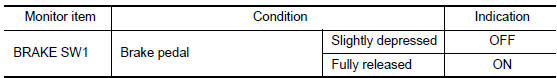
- Select "BRAKE SW1" in "DATA MONITOR" mode with CONSULT.
- Check "BRAKE SW1" indication under the following conditions.
Without CONSULT
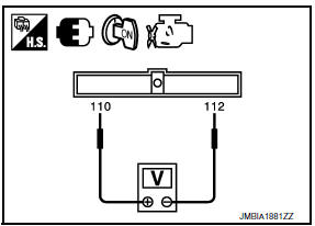
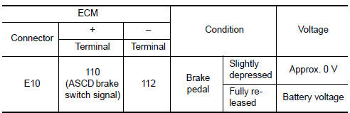
- Turn ignition switch ON.
- Check the voltage between ECM harness connectors
Diagnosis Procedure
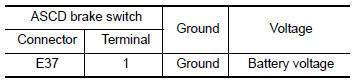
1.CHECK ASCD BRAKE SWITCH POWER SUPPLY CIRCUIT
- Turn ignition switch OFF.
- Disconnect ASCD brake switch harness connector.
- Turn ignition switch ON.
- Check the voltage between ASCD brake switch harness connector and ground.
2.DETECT MALFUNCTIONING PART
Check the following.
- Fuse block (J/B) connector E6
- Junction block connectors E44, E46
- 10 A fuse (No. 3)
- Harness for open or short between ASCD brake switch and fuse
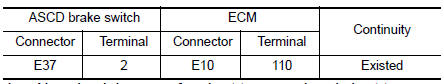
3.CHECK ASCD BRAKE SWITCH INPUT SIGNAL CIRCUIT FOR OPEN AND SHORT
- Turn ignition switch OFF.
- Disconnect ECM harness connector.
- Check the continuity between ASCD brake switch harness connector and ECM harness connector.
- Also check harness for short to ground and short to power.
4.DETECT MALFUNCTIONING PART
Check the following.
- Junction block connectors E45, E46
- Harness for open or short between ASCD brake switch and ECM
5.CHECK ASCD BRAKE SWITCH
6.CHECK INTERMITTENT INCIDENT
Component Inspection (ASCD Brake Switch)
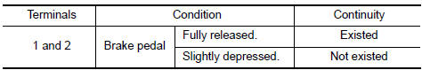
1.CHECK ASCD BRAKE SWITCH-I
- Turn ignition switch OFF.
- Disconnect ASCD brake switch harness connector.
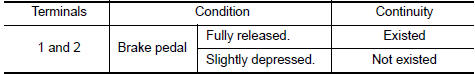
- Check the continuity between ASCD brake switch terminals under the following conditions.
2.CHECK ASCD BRAKE SWITCH-II
- Adjust ASCD brake switch installation. Refer to BR-14, "Inspection and Adjustment".
- Check the continuity between ASCD brake switch terminals under the following conditions
 P2138 APP sensor
Description
The accelerator pedal position sensor is installed on the upper end
of the accelerator pedal assembly. The sensor detects the accelerator
position and sends a signal to the ECM.
Ac ...
 ASCD indicator
Description
ASCD indicator lamp illuminates to indicate ASCD operation status. CRUISE is
integrated in combination
meter.
CRUISE illuminates when MAIN switch on ASCD steering switch is turned ...
Other materials:
Diagnosis system (audio unit)
Diagnosis Description
Self-diagnosis mode can perform the following items.
Versions display
Channel check diagnosis
Key check diagnosis
AV communication diagnosis
VERSIONS DISPLAY FUNCTION
Turn ignition switch ON.
Turn the audio unit off.
While pressing "1" button, turn vol ...
Off-road recovery
While driving, the right side or left side wheels
may unintentionally leave the road surface. If this
occurs, maintain control of the vehicle by following
the procedure below. Please note that this
procedure is only a general guide. The vehicle
must be driven as appropriate based on the conditi ...
Precautions
Precaution for Supplemental Restraint System (SRS) "AIR BAG" and "SEAT
BELT
PRE-TENSIONER"
The Supplemental Restraint System such as "AIR BAG" and "SEAT BELT
PRE-TENSIONER", used along
with a front seat belt, helps to reduce the risk or severity of injury to the
driver ...
Nissan Maxima Owners Manual
- Illustrated table of contents
- Safety-Seats, seat belts and supplemental restraint system
- Instruments and controls
- Pre-driving checks and adjustments
- Monitor, climate, audio, phone and voice recognition systems
- Starting and driving
- In case of emergency
- Appearance and care
- Do-it-yourself
- Maintenance and schedules
- Technical and consumer information
Nissan Maxima Service and Repair Manual

0.0069