Nissan Maxima Service and Repair Manual: Steering wheel
Inspection
INSTALLATION CONDITION
- Check installation conditions of steering gear assembly, front suspension assembly, axle and steering column assembly.
- Check if movement exists when steering wheel is moved up and down, to the left and right and to the axial direction.
- Check steering gear assembly bolts and nut for looseness.
STEERING WHEEL PLAY
- Turn steering wheel so that front wheels come to the straight-ahead position. Start engine and lightly turn steering wheel to the left and right until front wheels start to move. Measure steering wheel movement on the outer circumference.
- When the measurement value is outside the standard value, check backlash for each joint of steering column assembly and installation condition of steering gear assembly.
NEUTRAL POSITION OF STEERING WHEEL
- Make sure that steering gear assembly, steering column assembly and steering wheel are installed in the correct position.
- Perform neutral position inspection after wheel alignment. Refer to FSU-6, "Inspection and Adjustment".
- Set vehicle to the straight-ahead position and confirm steering wheel is in the neutral position.
- Loosen outer socket lock nut and turn inner socket to left and right equally to make fine adjustments if steering wheel is not in the neutral position.
STEERING WHEEL TURNING FORCE
- Park vehicle on a level, dry surface and set parking brake.
- Start engine.
- Bring power steering fluid up to adequate operating temperature.
Make sure the fluid temperature is approximately 50 - 80C (122 - 176F).
Tires need to be inflated to normal pressure.
- Check steering wheel turning force using Tool when steering wheel has been turned 360 degrees from the neutral position.
- If steering wheel turning force is out of specification, check rack sliding force.
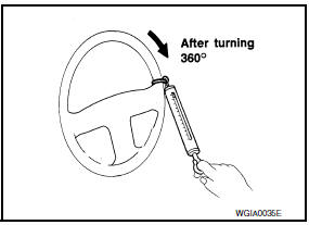
Tool number : - (J-44372)
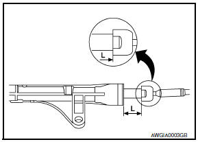
- While pulling outer socket slowly in +-11.5 mm (+-0.453 in) range from neutral position, make sure rack sliding force is within specification using Tool.
- If rack sliding force is not within specification, replace steering gear assembly.
Tool number : - (J-44372)
- If rack sliding force is OK, inspect steering column.
FRONT WHEEL TURNING ANGLE
- Check front wheel turning angle after toe-in inspection. Place
front wheels on turning radius gauges and rear wheels on stands.
Check the maximum inner and outer wheel turning angles for LH and RH road wheels.
- With the engine at idle, turn steering wheel from full left stop to full right stop and measure the turning angles.
- Measure rack stroke in neutral position if angles are outside the specified value.
 Power steering fluid
Inspection
FLUID LEVEL
Check fluid level with engine stopped.
Make sure that fluid level is between MIN and MAX.
Fluid levels at HOT (A) and COLD (B) are different. Do not confuse
them.
...
 Power steering oil pump
Inspection
CAUTION: Make sure that belt tension is
normal before starting the following procedure.
Connect the Tool between oil pump discharge connector and
high-pressure hose. Bleed air fro ...
Other materials:
Diagnosis and repair work flow
Work Flow
OVERALL SEQUENCE
DETAILED FLOW
1.GET INFORMATION FOR SYMPTOM
Get the detailed information from the customer about the symptom
(the condition and the environment
when the incident/malfunction occurred) using the "Diagnostic Work Sheet".
(Refer to EC-12, "Diagnostic ...
Vehicle information display
The vehicle information display is located to the
left of the speedometer. It displays such items as:
Home
Audio Information
Navigation Information
Drive Computer Information
Fuel Economy Information
Driving Aids Information (if so equipped)
Tire Pressure Information
Sport Inf ...
VDC/TCS/ABS
Symptom Table
If ABS warning lamp, SLIP indicator lamp turn ON, perform self-diagnosis.
NOTE:
1: The ABS does not operate when the speed is 10 km/h (6 MPH)
or less.
2: Under the following conditions, ABS is activated and
vibration is felt when brake pedal is lightly dep ...
Nissan Maxima Owners Manual
- Illustrated table of contents
- Safety-Seats, seat belts and supplemental restraint system
- Instruments and controls
- Pre-driving checks and adjustments
- Monitor, climate, audio, phone and voice recognition systems
- Starting and driving
- In case of emergency
- Appearance and care
- Do-it-yourself
- Maintenance and schedules
- Technical and consumer information
Nissan Maxima Service and Repair Manual

0.0062