Nissan Maxima Service and Repair Manual: B2267 engine speed
Description
The engine speed signal is transmitted from ECM to the combination meter via CAN communication.
DTC Logic
DTC DETECTION LOGIC
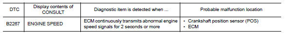
Diagnosis Procedure
1.PERFORM SELF-DIAGNOSIS OF ECM
Perform "Self Diagnostic Result" of ECM, and repair or replace malfunctioning parts.
>> Refer to EC-138, "CONSULT Function".
 DTC B2205 vehicle speed circuit
Description
The ABS actuator and electric unit (control unit) provides a vehicle speed
signal to the combination meter via
CAN communication lines.
DTC Logic
Diagnosis Procedure
Symptom: Dis ...
 B2268 water temp
Description
The engine coolant temperature signal is transmitted from ECM to the
combination meter via CAN communication.
DTC Logic
DTC DETECTION LOGIC
Diagnosis Procedure
1.PERFORM SELF-DIAG ...
Other materials:
Changing wheels and tires
Tire rotation
NISSAN recommends rotating the tires
every 5,000 miles (8,000 km).
For additional information on tire replacing
procedures, refer to "Flat tire" in the "In
case of emergency" section of this
manual.
As soon as possible, tighten the
wheel nuts to the specified torque
with ...
ABS branch line circuit
Diagnosis Procedure
1.CHECK CONNECTOR
Turn the ignition switch OFF.
Disconnect the battery cable from the negative terminal.
Check the terminals and connectors of the ABS actuator and
electric unit (control unit) for damage, bend
and loose connection (unit side and connector side).
...
B2602 shift position
Description
BCM confirms the shift position with the following 2
signals.
CVT selector lever
Speed signal from meter
DTC Logic
DTC DETECTION LOGIC
NOTE:
If DTC B2602 is displayed with DTC
U1000, first perform the trouble diagnosis for DTC U1000. Refer ...
Nissan Maxima Owners Manual
- Illustrated table of contents
- Safety-Seats, seat belts and supplemental restraint system
- Instruments and controls
- Pre-driving checks and adjustments
- Monitor, climate, audio, phone and voice recognition systems
- Starting and driving
- In case of emergency
- Appearance and care
- Do-it-yourself
- Maintenance and schedules
- Technical and consumer information
Nissan Maxima Service and Repair Manual

0.0052