Nissan Maxima Service and Repair Manual: DTC/circuit diagnosis
POWER SUPPLY AND GROUND CIRCUIT
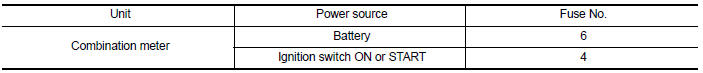
COMBINATION METER
COMBINATION METER : Diagnosis Procedure
Regarding Wiring Diagram information, refer to MWI-87, "Wiring Diagram".
1.CHECK FUSES
Check for blown combination meter fuses.
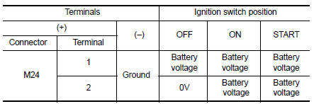
2.POWER SUPPLY CIRCUIT CHECK
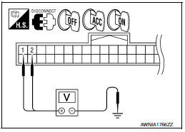
- Disconnect combination meter connector.
- Check voltage between combination meter harness connector M24 terminals 1, 2, and ground.
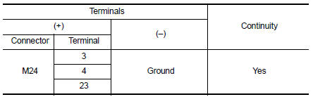
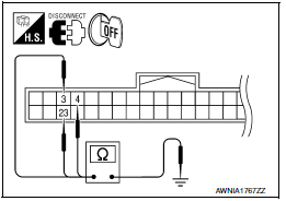
3.GROUND CIRCUIT CHECK
- Turn ignition switch OFF.
- Check continuity between combination meter harness connector terminals 3, 4, 23 and ground.
BCM (BODY CONTROL MODULE)
BCM (BODY CONTROL MODULE) : Diagnosis Procedure
Regarding Wiring Diagram information, refer to BCS-67, "Wiring Diagram".
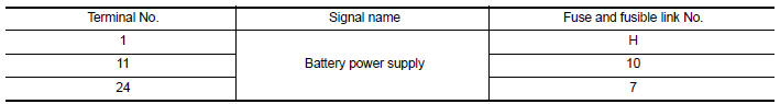
1. CHECK FUSE AND FUSIBLE LINK
Check if the following BCM fuses or fusible link are blown.
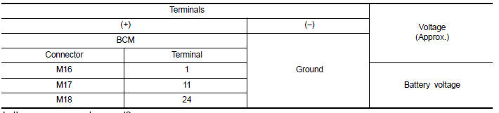
2. CHECK POWER SUPPLY CIRCUIT
- Turn ignition switch OFF.
- Disconnect BCM.
- Check voltage between BCM harness connector and ground.
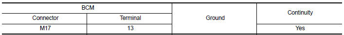
3. CHECK GROUND CIRCUIT
Check continuity between BCM harness connector and ground.
 Diagnosis system (BCM)
BUZZER
BUZZER : CONSULT Function (BCM - BUZZER)
DATA MONITOR
ACTIVE TEST
...
 Meter buzzer circuit
Description
The buzzer for warning chime system is installed in the
combination meter.
The combination meter sounds the alarm buzzer based on the signals
transmitted from various units.
...
Other materials:
Lock-up and select control system
System Diagram
System Description
The torque converter clutch piston in the torque converter is
engaged to eliminate torque converter slip to
increase power transmission efficiency.
The torque converter clutch control valve operation is controlled
by the torque converte ...
Check cooling fan relay
Description
The electrical load signal (Headlamp switch signal, rear window defogger
switch signal, etc.) is transferred via
the CAN communication line from BCM to ECM via the IPDM E/R.
Component Function Check
1.CHECK REAR WINDOW DEFOGGER SWITCH FUNCTION
Turn ignition switch ON.
Connec ...
Unit removal and installation
EPS CONTROL UNIT
Removal and Ins
REMOVAL
Disconnect negative battery terminal. Refer to PG-67, "Removal and
Installation (Battery)".
Remove audio display unit. Refer to AV-73, "Removal and
Installation" (BASE AUDIO), AV-161, "Removaland Installation" (BOSE
W/MONOCHROME DISPLAY), A ...
Nissan Maxima Owners Manual
- Illustrated table of contents
- Safety-Seats, seat belts and supplemental restraint system
- Instruments and controls
- Pre-driving checks and adjustments
- Monitor, climate, audio, phone and voice recognition systems
- Starting and driving
- In case of emergency
- Appearance and care
- Do-it-yourself
- Maintenance and schedules
- Technical and consumer information
Nissan Maxima Service and Repair Manual

0.0062