Nissan Maxima Service and Repair Manual: Seat belt buckle switch signal circuit
Description
Transmits a seat belt buckle switch LH signal to the combination meter.
Component Function Check
1. CHECK COMBINATION METER INPUT SIGNAL
- Start engine.
- Monitor seat belt warning lamp while fastening and unfastening the driver seat belt.
Diagnosis Procedure
Regarding Wiring Diagram information, refer to WCS-54, "Wiring Diagram".
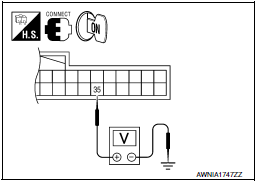
1. CHECK COMBINATION METER INPUT SIGNAL
- Turn ignition switch ON.
- Check voltage between combination meter harness connector M24 terminal 35 and ground.
2. CHECK SEAT BELT BUCKLE SWITCH LH CIRCUIT
- Turn ignition switch OFF.
- Disconnect combination meter and seat belt buckle switch LH.
- Check continuity between combination meter harness connector M24 terminal 35 and seat belt buckle switch LH harness connector B202 terminal 1.
- Check harness continuity between combination meter harness connector M24 terminal 35 and ground.
3. CHECK SEAT BELT BUCKLE SWITCH LH GROUND CIRCUIT
Check harness continuity between seat belt buckle switch LH harness connector B202 terminal 2 and ground.
Component Inspection
CHECK SEAT BELT BUCKLE SWITCH LH
- Turn ignition switch OFF.
- Disconnect the seat belt buckle switch LH connector.
- Check continuity between the seat belt buckle LH terminals 1 and 2.
 Meter buzzer circuit
Description
The buzzer for warning chime system is installed in the
combination meter.
The combination meter sounds the alarm buzzer based on the signals
transmitted from various units.
...

Other materials:
Programming trouble-diagnosis
If the HomeLink does not quickly learn the
hand-held transmitter information:
replace the hand-held transmitter batteries
with new batteries.
position the hand-held transmitter with its
battery area facing away from the
HomeLink surface.
press and hold both the HomeLink and
hand-hel ...
Center speaker
Description
The AV control unit sends audio signals to the BOSE speaker amp. The BOSE
speaker amp. amplifies the
audio signals before sending them to the center speaker using the audio signal
circuits.
Diagnosis Procedure
1.CONNECTOR CHECK
Check the AV control unit, BOSE speaker amp. and s ...
Vacuum lines
Exploded View
Clamp
Installation arrow
Vacuum hose
Vacuum pipe
Clip
To intake manifold
To brake booster
Front
Removal and Installation
REMOVAL
Disconnect the vacuum hose from the brake booster.
Disconnect the vacuum hose from the intake manifold.
Release the c ...
Nissan Maxima Owners Manual
- Illustrated table of contents
- Safety-Seats, seat belts and supplemental restraint system
- Instruments and controls
- Pre-driving checks and adjustments
- Monitor, climate, audio, phone and voice recognition systems
- Starting and driving
- In case of emergency
- Appearance and care
- Do-it-yourself
- Maintenance and schedules
- Technical and consumer information
Nissan Maxima Service and Repair Manual

0.0061