
Nissan Maxima Service and Repair Manual: Subwoofer
Removal and Installation
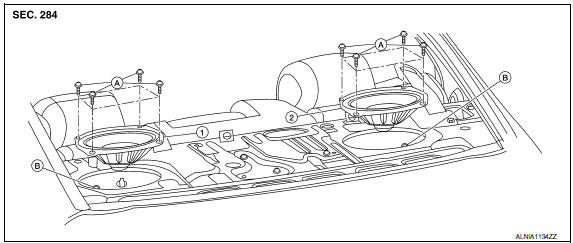
- Subwoofer LH
- Subwoofer RH
- Subwoofer screws
- Subwoofer connectors
REMOVAL
- Remove the rear parcel shelf finisher. Refer to INT-36, "Removal and Installation".
- Remove the subwoofer screws.
- Pull out the subwoofer, disconnect the harness connector from the subwoofer and remove.
INSTALLATION
Installation is in the reverse order of removal.
 Rear door speaker
Removal and Installation
REMOVAL
Remove the rear door finisher. Refer to INT-21, "Removal and
Installation".
Remove the rear door speaker screws (A).
Disconnect the harness connector (B) ...
 Subwoofer AMP
Removal and Installation
Subwoofer amp. and bracket
Subwoofer amp. bracket screws
REMOVAL
Disconnect the battery negative terminal. Refer to PG-67, "Removal
and Installation (Batt ...
Other materials:
Front combination lamp
Disassembly and Assembly
EXPLODED VIEW
Front combination lamp
Xenon bulb
Plastic cover
Side marker lamp socket
Side marker lamp bulb
Front turn signal lamp socket
Front turn signal lamp bulb
Halogen bulb socket (high beam)
Halogen bulb (high beam)
HID control unit and ...
Precaution
PRECAUTIONS
Precaution for Supplemental Restraint System (SRS) "AIR BAG" and "SEAT
BELT
PRE-TENSIONER"
The Supplemental Restraint System such as "AIR BAG" and "SEAT BELT
PRE-TENSIONER", used along
with a front seat belt, helps to reduce the risk or severity of injury to ...
Mechanical system
Cross-Sectional View
Converter housing
Oil pump
Forward clutch
Reverse brake
Planetary carrier
Primary pulley
Steel belt
Sun gear
Side cover
Internal gear
Secondary pulley
Final gear
D ...
Nissan Maxima Owners Manual
- Illustrated table of contents
- Safety-Seats, seat belts and supplemental restraint system
- Instruments and controls
- Pre-driving checks and adjustments
- Monitor, climate, audio, phone and voice recognition systems
- Starting and driving
- In case of emergency
- Appearance and care
- Do-it-yourself
- Maintenance and schedules
- Technical and consumer information
Nissan Maxima Service and Repair Manual

0.0156