Nissan Maxima Service and Repair Manual: Front passenger air bag module
Removal and Installation
CAUTION:
- Before servicing, turn ignition switch OFF, disconnect both battery terminals and wait at least 3 minutes.
- Do not use air tools or electric tools for servicing.
- Always work from the side of air bag module. Do not work from the front of it.
- Always place air bag module with pad side facing upward.
- Do not cause impact to the air bag module by dropping etc. Replace the air bag module if it has been dropped or sustained an impact.
REMOVAL
- Disconnect the negative and positive battery terminals, then wait at least 3 minutes. Refer to PG-67, "Removal and Installation (Battery)".
- Remove the glove box assembly. Refer to IP-20, "Removal and Installation".
- Disconnect the harness connector (A) from the front passenger air bag module. NOTE: The figure shows installed condition of the front passenger air bag module without glove box in place.
- Remove front passenger air bag module bolt (B) from steering member (1).
- Remove the remaining instrument panel from the vehicle. Refer to IP-19, "Removal and Installation".
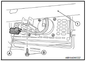
Front passenger air bag module bolt (B) : 22.3 N*m (2.3 kg-m, 16 inlb)
- Remove the front passenger air bag module screws (A).
 : Front
- Release the upper and lower front passenger air bag module tabs (A) from instrument panel and pad assembly (1).
- Rotate and lift the front passenger air bag module away from the instrument panel, then remove.
INSTALLATION
CAUTION:
- Do not use old bolts after removal; replace with new bolts.
- Be careful not to damage the harness while installing.
- After the work is completed, make sure no system malfunction is detected by air bag warning lamp.
- - In case a malfunction is detected by the air bag warning lamp, reset with the self-diagnosis function and delete the memory by CONSULT.
- If a malfunction is still detected after the above operation,
perform self-diagnosis to repair malfunctions.
Refer to SRC-12, "SRS Operation Check".
- Install front passenger air bag module to the instrument panel assembly.
- Install the instrument panel assembly. Refer to IP-19, "Removal and Installation".
- Connect the front passenger air bag module harness connector to yellow 4-pin service replacement connector and fasten to mounting bracket.
 Spiral cable
Removal and Installation
CAUTION:
Before servicing, turn ignition switch OFF, disconnect both
battery terminals and wait at least 3 minutes.
Do not use air tools or electric tools for serv ...
 Side curtain air bag module
Component
Side curtain air bag module tether
Side curtain air bag module assembly
Side curtain air bag module inflator
Front
Removal and Installation
CAUTION:
Before servicing ...
Other materials:
Subwoofer
Description
The AV control unit sends audio signals to the BOSE speaker amp. The BOSE
speaker amp. amplifies the
audio signals before sending them to the subwoofers using the audio signal
circuits.
Diagnosis Procedure
1.CONNECTOR CHECK
Check the AV control unit, BOSE speaker amp. and subwo ...
Three-point type seat belt with retractor
WARNING
Every person who drives or rides in this
vehicle should use a seat belt at all
times. Children should be in the rear
seats and in an appropriate restraint.
Do not ride in a moving vehicle when
the seatback is reclined. This can be
dangerous. The shoulder belt will not
be ag ...
Outside the vehicle
The maintenance items listed here should be
performed from time to time, unless otherwise
specified.
Doors and engine hood: Check that the doors
and engine hood operate properly. Also ensure
that all latches lock securely. Lubricate hinges,
latches, latch pins, rollers and links if necessary ...
Nissan Maxima Owners Manual
- Illustrated table of contents
- Safety-Seats, seat belts and supplemental restraint system
- Instruments and controls
- Pre-driving checks and adjustments
- Monitor, climate, audio, phone and voice recognition systems
- Starting and driving
- In case of emergency
- Appearance and care
- Do-it-yourself
- Maintenance and schedules
- Technical and consumer information
Nissan Maxima Service and Repair Manual

0.0052