Nissan Maxima Service and Repair Manual: On board diagnostic (OBD) system
Trouble Diagnosis Introduction
CAUTION:
- Do not use electrical test equipment on any circuit related to
the SRS unless instructed to do so in
this Service Manual. SRS wiring harnesses can be identified by yellow and/or orange harness connectors. - Do not attempt to repair, splice or modify SRS wiring
harnesses. If a harness is damaged, replace it
with a new one. - Keep ground connections clean.
DIAGNOSIS FUNCTION
The SRS self-diagnosis results can be read by using "AIR BAG" warning lamp
and/or CONSULT.
The User mode is exclusively prepared for the customer
(driver). This mode warns the driver of a system malfunction
through the
operation of the "AIR BAG" warning lamp.
The Diagnosis mode allows the
technician to locate and inspect the malfunctioning part.
The mode
applications for the "AIR BAG" warning lamp and CONSULT are as follows:

HOW TO PERFORM TROUBLE DIAGNOSES FOR QUICK AND ACCURATE REPAIR
A good understanding of the malfunction conditions can make troubleshooting
faster and more accurate.
In general, each customer feels differently about a
malfunction. It is important to fully understand the symptoms
or conditions
for a customer complaint.
Information From Customer
WHAT - Vehicle model<>
WHEN - Date, Frequencies<>
WHERE - Road
conditions<>
HOW - Operating conditions, Symptoms
Preliminary Check
Check that the following parts are in good order.
- Battery
- Fuse
- System component-to-harness connections
SRS Operation Check
DIAGNOSTIC PROCEDURE 1
Checking SRS Operation Using "AIR BAG" Warning Lamp-User Mode
- Turn the ignition switch from OFF to ON, and check that the air bag warning lamp blinks.
- Compare the SRS air bag warning lamp blinking pattern with the
examples.
SRS Air bag warning lamp examples
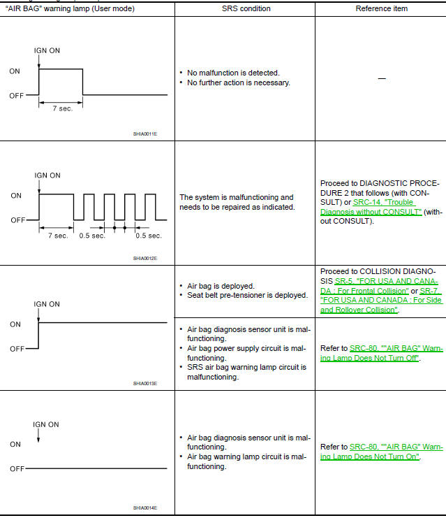
DIAGNOSTIC PROCEDURE 2
- Connect CONSULT.
- Diagnostic code is displayed on "SELF-DIAG [CURRENT]".
If no malfunction is detected on "SELF-DIAG [CURRENT]", but malfunction is
detected in "SRS Operation
Check" using the "AIR BAG" warning lamp, the
following cases may exist:
- "SELF-DIAG [PAST]" memory might not be erased.
- The SRS system malfunctions intermittently.
Perform DIAGNOSTIC PROCEDURE 4. Refer to SRC-14, "Self-Diagnosis Function (Without CONSULT)".
Trouble Diagnosis without CONSULT
DIAGNOSTIC PROCEDURE 6
Inspect SRS Malfunction Using "AIR BAG" Warning Lamp-Diagnosis Mode
NOTE:
SRS will not enter Diagnosis mode if
no malfunction is detected in User mode.
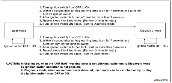
- Turn ignition switch ON.
- After "AIR BAG" warning lamp lights for 7 seconds, turn ignition switch OFF within 1 second.
- Wait more than 3 seconds.
- Repeat steps 1 to 3 two more times (3 times total).
- Turn ignition switch ON.
SRS is now in Diagnosis mode. Refer to SRC-56, "Trouble Diagnosis without CONSULT".
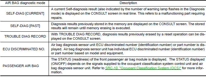
CONSULT Function (AIR BAG)
CONSULT can display each diagnostic item using the diagnostic test modes shown.
Self-Diagnosis Function (Without CONSULT)
- The reading of these results is accomplished using one of two modes -"User mode" and "Diagnosis mode".
- After a malfunction is repaired, turn the ignition switch OFF for at
least one second, then back ON. Diagnosis
mode returns to the User mode. At that time, the self-diagnostic result is cleared.
HOW TO CHANGE SELF-DIAGNOSIS MODE
DIAGNOSTIC PROCEDURE 3
Final Check of SRS Using CONSULT - Diagnosis Mode
- Connect CONSULT.
- If no DTC is detected on "SELF-DIAG [CURRENT]", repair of SRS is
completed. Go to step 3.
If any DTC is detected on "SELF-DIAG [CURRENT]", the malfunctioning part has not been repaired completely
or another malfunctioning part is being detected. Perform DIAGNOSTIC PROCEDURE 2. Refer to
SRC-12, "SRS Operation Check". - Touch "ERASE".
NOTE:
Touch "ERASE" to clear the memory of the malfunction ("SELF-DIAG [PAST]").
If the memory of the malfunction in "SELF-DIAG [PAST]" is not erased, the User mode shows the system
malfunction by the operation of the warning lamp even if the malfunction is repaired completely. - Touch "BACK" key of CONSULT. Touch "SELF-DIAG [PAST]".
- Check that no malfunction is detected on "SELF-DIAG [PAST]".
- Touch "BACK" key of CONSULT to return to User mode from Diagnosis mode.
- Turn ignition switch OFF and then turn off and disconnect CONSULT.
- Go to SRC-12, "SRS Operation Check".
DIAGNOSTIC PROCEDURE 4
Check SRS Repair History
1.CONSIDER POSSIBILITY THAT SELF-DIAGNOSTIC RESULT WAS NOT ERASED AFTER REPAIR
Check repair history of the SRS.
 Passenger seat belt warning system
System Diagram
System Description
The seat belt warning lamp (1) will remind the driver if the driver or
front passenger seat belt should be buckled. The system works inconjunction
with the o ...

Other materials:
System temporarily unavailable
Condition A
When the radar sensor picks up interference
from another radar source, making it impossible
to detect a vehicle ahead, the FEB system is
automatically turned off.
The FEB system warning light (orange) will illuminate.
Action to take
When the above conditions no longer exist, ...
C1716 - C1719 transmitter pressure malfunction
Description
Air pressure data from one or more transmitters is out of range.
DTC Logic
NOTE: The Signal Tech II Tool (J-50190) can
be used to perform the following functions. Refer to the Signal Tech II User
Guide for additional information.
Display tire pressure reported by the TPM ...
Break-in schedule
CAUTION
During the first 1,200 miles (2,000 km),
follow these recommendations to obtain
maximum engine performance and ensure
the future reliability and economy of your
new vehicle. Failure to follow these recommendations
may result in shortened
engine life and reduced engine
performance.
...
Nissan Maxima Owners Manual
- Illustrated table of contents
- Safety-Seats, seat belts and supplemental restraint system
- Instruments and controls
- Pre-driving checks and adjustments
- Monitor, climate, audio, phone and voice recognition systems
- Starting and driving
- In case of emergency
- Appearance and care
- Do-it-yourself
- Maintenance and schedules
- Technical and consumer information
Nissan Maxima Service and Repair Manual

0.0078